Friday, December 15, 2017

WEEK 6: Hardware Development - 1

As the proposed title of the project is 
Development of Electronic Stethoscope with Phonocardiogram Display, 
some modifications has been made towards the stethoscope that is seen today in the market. 

In adaptation to the project, a condensed microphone is slit through to a see through plastic tube in order to give a clear vision of how the microphone collects the signal from the chest piece of  the stethoscope. Thus,the chest piece was removed from the ear piece , and only have the chest piece tube to be connected towards the condensed microphone. 

Figure below shows the development that has been made to adapt to the project objectives.  


This figure below shows when the chest piece and the condensed microphone is put together. In order to achieve the objective no. 1, which are to develop electronic stethoscope by using condensed microphone through a chest piece.


WEEK 5: Power amplifier circuit

Since the sound from the heart showing small signal thus in amplifying the signal of the heart sound, power amplifier circuit is needed.

 The op-amp chosen to be the amplifier is LM-386 since it amplify low noise, and the amplifier cater for low noise voltage amplifier. So, it is suitable for this project and it will make the sound audible.
Since the gain are from 20-200, then it is effective enough for the amplifier to amplify the heart sound since the heart sound frequency is in that range.

The figure below shows the 8 pin-out including labels of the op-amp. 
The inputs are ground referenced while the output automatically biases to one-half the supply voltage. The quiescent power drain is only 24 mW when operating from a 6-V supply, making the LM-386 is ideal for battery operation. 
Moreover it make it more suitable for this project since, this product is going to get the power supply by 9V battery.


Amplifiers can be thought of as a simple box or block containing the amplifying device, such as a TransistorField Effect Transistor or Op-amp, which has two input terminals and two output terminals (ground being common) with the output signal being much greater than that of the input signal as it has been “Amplified”.

Table below shows the classification of amplifiers.
Type of SignalType of
Configuration
Frequency of
Operation
Small SignalCommon EmitterClass A AmplifierDirect Current (DC)
Large SignalCommon BaseClass B AmplifierAudio Frequencies (AF)
Common CollectorClass AB AmplifierRadio Frequencies (RF)
Class C AmplifierVHF, UHF and SHF
Frequencies

Monday, October 30, 2017

WEEK 4: The stethoscope

A stethoscope is also the main part of the project. 
Since i'm going to modified the traditional circuit to the electronic one, so we only need the chest piece part as the collector for the input/signal. 
The chest piece of the stethoscope will be cut off from the  tube through the ear tip. 
A microphone will be inserted near the chest piece tube then this part will be connected to the amplifier circuit.
Thus, the chest piece part of the stethoscope will be the place where the input signal of the heart sound is collected.

I have chose this stethoscope to be part of my project. The price is quite reasonable in the market since there are a lot of types and brands out there. So, the stethoscope is like in the picture.
The chest piece is in a good condition, hopefully it will work well with the circuit assemble later.


Tuesday, October 24, 2017

WEEK 3: Testing the circuit

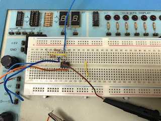
The circuit was assembled on the breadboard to be tested. 
The pre-amplifier circuit was tested first. To see whether it amplify enough or not.
The input was taken from the trainer and set to 9V. 
Then the circuit was connected to the oscilloscope to see the amplified wave. 
The wave is set to sine wave so that to make it clear to see the change in amplitude of the sine wave that determine the input is amplified.

Below is the circuit assembled with only the pre-amplifier circuit.

Below is the input, and the Pk-pk value is 1.00V.


Below is the output, and the Pk-pk value is 21.60V.


WEEK 2: Designing the Amplifier Circuit

  For the amplifier circuit, there are 2 parts, which are,
 pre-amplifier --> low pass filter
Both uses the same IC in order to amplify/filter. Since the op-amp has amplify enough the input sound thus we don't need to apply another circuit which is power amplifier where the sound is power amplify again to make it more audible/clear to be heard.
The circuit is one of the electronic part for this project.

Below is the circuit shows the pre-amplifier circuit and low pass filter.


The input was put in at the pre-amplifier part then the output is taken after the it has been filter in the low pass filter circuit. The gain was calculated and since the pre-amplifier part is inverting amplifier thus it is less input impedance than non-inverting amplifier.

Since, the input is low-noise so the input impedance is need to be low. This is because the noise current can generate large voltage drops otherwise.

Monday, October 16, 2017

WEEK 1 : Choosing the suitable IC for Operational Amplifier

Choosing the suitable OP-amp is one of the most crucial part in this project. Since the sound of the heart is not audible directly to human ear, so we need to amplify the sound so it is suitable and capable to be heard by human ear. Specific operational amplifier is going to be used so that the sound is amplified with the desire amount.

The integrated circuit (IC) that was chosen as the operational amplifier was TL072CN
it is a low noise amplifier, since the heart sound is in low noise range which is only 1 - 1.67 Hz.
Choosing  TL072CN as the OP-amp it has low harmonic distortion and low noise making this IC an ideally suited for high-fidelity and audio specifically in amplifying the heart sound that is in low frequency.

 In order to make it audible this project is made so that it will help in amplifying the sound. Most importantly is this electronic part.


Figure 1: The pinout label of the IC of TL072CN


Tuesday, September 26, 2017

Final Year Project 2

For this semester, this project will be continue with developing the prototype of the
 Electronic Stethoscope with Phonocardiogram Display.
 
Much work is needed to be put in with the help and guidance from my supervisor, Sir Zubir the project will be much more edible for me to produce the prototype. 

Thus, to achieve the requirement for my Final Year Project 2, Semester 2, 2017.


WEEK 14 - Presentation Day and Report Writing

The presentation day was held on 15th November 2017 at Gemilang Hall UniKL BMI. The event started at 8am. The assesssors for this project wa...